Wednesday 29 June 2016

What is Level-Shifter cells ?


Two interacting power domains may also be operating with different voltage ranges. In this case, a logic 1 value might be represented in the driving domain using a voltage that would not be seen as an unambiguous 1 in the receiving domain. i.e receiving domain might treat it as 0 due to high operating voltage .

Level-Shifters are inserted at a domain boundary to translate from a lower to a higher voltage range, and sometimes from a higher to a lower voltage range as well. The translation ensures the logic value sent by the driving logic in one domain is correctly received by the receiving logic in the other domain.

Level-Shifter cells are functionally similar to Buffer cell.


Types of Level-Shifter Cells :

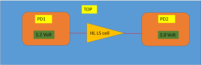
1. HL : High to Low type of LS cell is required when source domain is operating at high voltage and sink domain is working at low voltage in any specific state of PST(Power-State Table).


2. LH : Low to High  type of LS cell is required when source domain is operating at low voltage and sink domain is working at high voltage in any specific state of PST(Power-State Table).


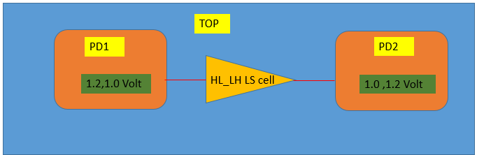
3. HL_LH : This is the type of LS cell which will serve both purpose i.e it can convert signal voltage to low to high and vice versa. This type of cell is mainly required when in 1 PST state source domain is operating at high voltage and sink domain is working at low voltage while in another PST state source domain is operating at low voltage and sink domain is working at high voltage.


Liberty attributes of LS cell :

  • is_level_shifter : true;  
    • This attribute says that it is LS type cell.
  • level_shifter_type : LH; 
    • This attribute says it is LS cell of of type LH.

What is ELS (Enable-Level Shifter) cell ?

Enable-Level Shifter cells often termed as ELS cells. This are cells which has the functionality of both Isolation and Level-shifter cells. In general this will serve the purpose of both isolation and level-shifting in Power-Aware designs .

This will have the advantage that it will occupy less area compared to separate isolation and level-shifter cell.

Why State retention (Retention) is required in Power-Aware Design ?


  • State retention is the ability to retain the value of a state element in a power domain while switching off the primary power to that element, and being able to use the retained value as the functional value of the state element upon power-up. 

  • State retention can enable a power domain to return to operational mode more quickly after a power-down/power-up sequence and it can be used to maintain state values that cannot be easily recomputed on power-up. State retention can be implemented using retention memories or retention registers. Retention registers are sequential elements (latches or flip-flops) that have state retention capability.

What is Isolation cells in Power aware Design?


Why Isolation cell is required in Power Aware Design?
  • Two power domains interact if one contains logic that is the driver of a net and the other contains logic that is a receiver of the same net. When both power domains are powered up, the receiving logic should always see the driving logic’s output as an unambiguous 1 or 0 value, except for a very short time when the value is in transition. The structure of CMOS logic typically ensures that minimal current flow will occur when the input value to a gate is a 1 or 0. However, if the driving logic is powered down, the input to the receiving logic may float between 1 or 0. This can cause significant current to flow through the receiving logic, which can damage the circuit. An undriven input can also cause functional problems if it floats to an unintended logic value.
  • To avoid this problem, isolation cells are inserted at the boundary of a power domain to ensure that receiving logic always sees an unambiguous 1 or 0 value. Isolation may be inserted for an input or for an output of the power domain. An isolation cell operates in two modes: normal mode, in which it acts like a buffer, and isolation mode, in which it clamps its output to a defined value. An isolation enable signal determines the operational mode of an isolation cell at any given time.

Types Of Isolation Cells :

Depending upon the need of user , There are mainly three types of isolation cells.

1. Isolation cell with clamp_value 1:
  • This type of Isolation cells will have function such that it will have o/p of logic 1 , when it is in isolation mode. And when it is in non-isolation mode it will act as buffer i.e simply pass the data to o/p. This is similar to OR gate.
2. Isolation cell with clamp_value 0:
  • This type of Isolation cells will have function such that it will have o/p of logic 0 , when it is in isolation mode. And when it is in non-isolation mode it will act as buffer i.e simply pass the data to o/p.This is similar to AND gate.
3. Latch type Isolation cell:
  • This type of Isolation cells will have function such that it will latch the o/p of isolated port when it is in isolation mode. And when it is in non-isolation mode it will act as buffer i.e simply pass the data to o/p.This is similar to Latch.

Types of Retention Cells

Depending on how the retained value is stored and retrieved/restored , there are at least two flavors of retention registers, as follows:

1) Balloon-style retention: In a balloon-style retention register, the retained value is held in an
additional latch, often called the balloon latch. In this case, the balloon element is not in the
functional data-path of the register. 

2) Master/slave-alive retention: In a master/slave-alive retention register, the retained value is held in the master or slave latch. In this case, the retention element is in the functional data-path of the
register.

  • Ballon-style retention can be Dual-Pin Retention cell or Single-Pin Retention cell. 
  • Master/slave-alive retention is same as Zero-Pin Retention cell.

Dual-Pin Retention :
  • Dual-Pin Retention is the one which has two separate control signal for save and restore operation. 
  • Save operation can be level-sensitive or edge-sensitive.

Single-Pin Retention:
  • Single-Pin Retention is the one which has single control signal for both save and restore operation. 
  • Save operation can be level-sensitive or edge-sensitive.
  • Save operation and Restore operation will be on opposite level/edge of control signal. i.e If save is performed on level high than restore will be performed on level low of control signal.

Zero-Pin Retention:
  • Zero-Pin Retention is the one which does not have any control signal .
  • Save operation will be performed when the power domain in which cell is sitting goes from NORMAL to CORRUPT state. 
  • Restore operation will be performed when the power domain in which cell is sitting goes from CORRUPT to NORMAL state.